
By Robert Peniowich, SMT Corp Electrical Lab Manager
While the core testing methods defined in SAE AS6171 Moderate Risk Level 2 (MRL2) can be used to provide invaluable insights regarding the chemical and physical properties of components (External Visual Inspection, Radiological Inspection, XRF, Decapsulation), these methods do not support a determination of whether the components will function as intended by the original component manufacturer (OCM), and by extension, perform per end-customer requirements. Only by the addition of functional and performance testing, can more sophisticated counterfeits, such as clones, be effectively detected. Additionally, only electrical functional and performance testing can reliably detect quality issues that have manifested as degraded device performance.
Given the relatively long mission life for products and systems used in aerospace and defense applications, components sourced from the open market can often be 10-20+ years old. These components may have changed hands numerous times with no traceability and little to no way to determine how devices have been stored and handled. Electrical testing provides a mechanism to verify whether these components meet OCM/customer specifications. In some cases, components which are verified to be authentic per AS6171 visual and mechanical testing, can have defects that only manifest as out of specification electrical parameters. Also, the counterfeit market is consistently advancing methods to clone and model electrical, electronic, and electromechanical (EEE) components. Electrical testing is a critical tool for identifying suspect counterfeit devices.
AS6171 MRL2 recommends a minimum static DC electrical testing for “Active Complex” and “Active Simple” components and value measurements for passive components. Static DC electrical testing typically consists of measurements of input/output leakage currents, input and output voltages levels, and static supply currents. Value measurements for passive components include parameters such as resistance (for resistors) and capacitance (for capacitors). For Active Complex or Active Simple components, verifying electrical functionality is the first step required to measure various DC and/or AC electrical parameters. Testing for electrical functionality varies by device type/family. As an example, testing the read, write, and erase operations for FLASH memory, or the logic table for a NAND gate are basic functional tests.
Electrical Functional Testing
During functional testing, the input and output voltage levels can be controlled and measured to verify the device functionally operates within the limits specified by the OCM. Additionally, electrical testing can verify the component manufacturer’s identifier written to the device’s memory. This verification is used across a manufacturing lot of components to ensure all devices in the lot match each other, as well as what is specified in the datasheet. If a device under test has non-volatile memory, memory banks can be read back to verify the contents match the factory default. A memory verification check can determine if a device has been previously programmed, which cannot be otherwise identified.
Electrical testing can identify the primary component value, resistance or capacitance, and validate the tolerance of the component under test. Evidence gathered during AS6171 visual, material, and mechanical testing can corroborate the test results in AS6171 electrical testing.
Electrical Testing as a Quality Verification
Electrical testing is an extension of the component quality inspection process. An authentic part can pass AS6171 visual, material, and mechanical test methods but fail AS6171 electrical testing. Recently, SMT Corp performed AS6171 MRL2 (with electrical) testing of a three-phase bridge rectifier, which is six Schottky diodes in a specific arrangement. The components were obsolete and no longer available through the OCM or franchise distribution. They were only available from one known source on the open market.
SMT Corp performed testing in accordance with the customer’s testing flow-downs, AS6171 visual and mechanical tests. The devices passed all authentication testing including XRF Lead Finish Analysis, Scanning Electron Microscopy, and Decapsulation. However, when the components were subjected to electrical testing, approximately 50% of the parts failed. Further investigation was conducted into the electrical failures which concluded that the components were experiencing a physical breakdown during the reverse leakage test. In this test, a voltage is applied to the device and incrementally increased to the limit specified in the device datasheet. During the application of voltage, the current through the device is measured. When the current exceeds the maximum limit noted in the datasheet, the test terminates, and the component is marked as a failure. The failing components were found to exceed the maximum current allowed at varying levels of the applied voltage.
This type of failure indicates the likelihood of prior component mishandling and/or potential electrostatic discharge (ESD) events that occurred in the past resulting in damage or the premature degradation of the device. Due to the physical characteristics of a diode, none of these findings would have been identified through SAE AS6171 visual, mechanical, or material authentication methods. Only by applying a controlled voltage and monitoring the current could these results be found.
Electrical Testing as an Augmentation of Authenticity Verification
Electrical testing also augments AS6171 visual, mechanical, and material testing methods by providing the ability to verify a component’s speed grade. Xilinx FPGAs, for example, indicate the speed grade in the part number as well as on the silicon die. By operating a device at its programmed frequency, SMT Corp can determine the component’s speed grade. By measuring setup and hold times and propagation delays and comparing them to the switching characteristics provided by the OCM, a device under tests speed grade can be determined.
Passive devices such as resistors and capacitors can be misrepresented by incorrect labels or part markings that indicate a different value than what they are. This is especially true when the device is too small for any type of marking, color band or ink marking. For example, a 10% tolerance resistor could be passed off as a more expensive 1% or 0.1% tolerance resistor.
While performing AS6171 MRL2 testing on surface mount diodes, the device under test was too small for a manufacturing part marking, specifically, the part number suffix which identifies the voltage rating. Because of this, the voltage rating could not be verified through visual means. A diodes voltage rating is a key parameter because this value specifies the maximum voltage at which it can functionally operate. SMT Corp successfully verified the voltage rating of the component through electrical testing.
Electrical Up-screening and MIL-STD-883/MIL-STD-750 Testing
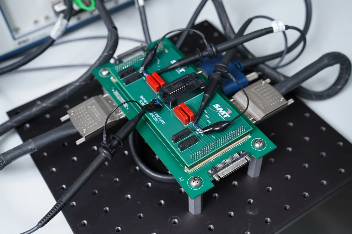
An EEPROM subjected to a temperature up-screen would have a read and write cycle performed at maximum cold and hot temperatures as well as ambient (+25°C) at maximum frequency. At each temperature range the same test sets are performed and the data collected. This data is then compared against the OCM datasheet to determine a passing or failing component. The following is a PCBA designed by SMT Corp engineers used in the up-screening of an EEPROM device. Parameters such as input and output leakage current are extremely susceptible to temperature changes and are closely monitored. Other sensitive parameters include supply currents and propagation delays.
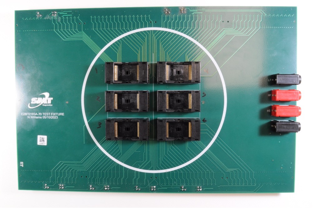
Multi-site Flash Memory Up-Screen
All types of electrical components, from passives to actives, have associated temperature ranges which indicate the guaranteed windows of operation. These operating ranges typically are Commercial (0°C to + 70°C), Industrial (-40°C to +85°C), and Military (-55°C to +125°C). Electrical testing can be used to verify a component’s operation and value measurements over the specified temperature range for the device. In other cases, an up-screen can be performed in which the component is pushed past the operational range specified by the OCM’s datasheet to determine if the device’s performance is still within specified limits. An example would be operating a commercial temperature grade device at an industrial temperature operating range. This type of testing would verify every parameter of the device at both temperature extremes to ensure full device functionality and performance.
MIL-STD-883 and MIL-STD-750 are two standards that establish test methods for environmental, physical, and electrical characteristics of semiconductor devices for use in military and aerospace applications. These tests include constant acceleration, in which the mechanical limits of the device package are placed under stress via high acceleration (30,000 g) forces. Another test method prescribed in MIL-STD-883 is thermal cycling, which will determine a part’s resistance to extremes of high and low temperatures and to alternate exposures of these extremes. The device under test is then visually and electrically tested to check for damage or loss of functionality. Components designated for military use will have an associated MIL-PRF document (e.g. MIL-PRF-38534, and MIL-PRF-38535) that appoints which MIL-STD-883/750 test is applicable for that device. Commercial off-the-shelf components considered for military use are required to be up-screened to these standards.
Post test inspection is crucial when validating a components temperature grade as identified during visual inspection. A suspect counterfeit or clone device that was previously screened to commercial temperature could experience significant failure rates if exposed to industrial temperatures, which could only be verified through this test.
Electrical testing over temperature is one method to verify the functionality of a device over the defined temperature range. Burn-in testing is another method to detect component failures after being operated at maximum operating temperatures for an extended period of time. This testing technique stresses a component at its highest rated temperature anywhere from 12 to 352 hours per MIL-STD-883 Test Method 1015.12. Once burn in has been completed, devices are electrically re-tested to check for electrical failures and/or changes to key electrical parameters, which could result in failure.
Burn-in testing is intended to screen out components that may be prone to early life failures or are very close to end of life failure. Devices that fail burn-in can pass standard temperature testing as well as authentication testing. Burn-in testing can be used as two different tests depending on the flow down of the component being tested. Burn-in screening for MIL designated components is to screen devices at maximum operating limits prior to deploying a device into an extreme environment where a device failure could result in mission failure, product failure, safety issues, or loss of life. In the world of component obsolescence, burn-in testing is a good methodology to determine if the components are at the end of their lifespan. Adding burn-in testing with obsolescence quality inspection, further aids in making a final declaration to the quality of the device under test.
Conclusion
Electrical testing provides a crucial step in determining the quality and authenticity of a EEE device. Data collected by electrical functional and performance testing can be used to detect the likelihood for failure due to component mistreatment, or clones and counterfeits. When used in conjunction with AS6171 visual, mechanical and material authentication methods, electrical testing provides the final piece of the puzzle to know all aspects of the component.
SMT Corp is a highly accredited and recognized expert in electrical testing
Get expert advice on mitigating the risk of counterfeit, cloned, altered and substandard products from entering your supply chain